PV103R Pump Unit
Since the introduction of the PV103R in March 1994 there have been four build standards.With all four build standards there are two variants, the rack and flightline. Each standard hasimproved either the performance and reliability or extended the servicing period.The PV 103R rack-mounted variant provides pressure and vacuum supplies for use with other rack-mounted equipment (such as the ADTS 405) as part of an instrument and air data component servicing and testing facility. Alternatively the unit can be fitted in a trolley as part of a mobile air data test system.
Item:3-10a†;Description:.Screw, M4x 30, QTY:4
Item:3-10a†;Description:.Pipe assembly QTY:1
Item:3-10a†;Description:.Cable looms, assembly;Manufacturer's Part Number:AS405-24-1728M1;QTY:1
3.Release the water drain trap from the spring clip, remove the drain pipe from the clear nylon bowl. Discard the water drain trap. Unscrew and remove the two screws securing the spring clip, discard the screws and spring clip.
4.Unscrew and remove the clips retaining the cooling coil. Discard the cooling coil and clips.
5.Front panel;Note:Take appropriate precautions to prevent swarf contamination of the unit from the following procedure. [Service tip - turn unit upside down when drilling.]
8.Connect the new pressure output pipe to the output port of the pump head. Connect the other end to the input connection of the water/cooler assembly.
9.Connect the new pipe to the output union of the water drain trap and the output connection of the rear panel. Connect the water drain pipe, make sure the other end locates in the grommet for correct venting of the water/cooler assembly.
10.Carry out an inspection of the unit look for loose connections and/or disturbance of the internal components.
11.Carry out a Standard Serviceability Test detailed in Chapter 5.
银飞 sells PV103R Pump Unit
PV103R Introduction
1.Water drain filter
2.Pneumatic output connections
3.Pump and Motor assembly
4.Fan assembly
5.Motor controller PCB
6.Power supply filter connector
7.Power supply unit
8.Elapsed time indicator
9.Fuse holder
10.Switch
11.Filter
Specification Build standard 1
Input:Power supply
............................................................ 90 - 230 Vac 50 - 60 Hz (nominal)
........................................................................110 Vac, 400 Hz (nominal)
......................................................................... continuous rating 300 VA
Output:
Pressure (min) ........................................................ 3.5 bar abs (100 inHg abs)
Airspeed rate ......................................................... 1 Mach/min up
...................................................... (into a volume of 10 litres {600 cu in})
.................................................................. 900 knots/min up to 850 knots
........................................................ (into a volume of 2 litres {120 cu in})
Vacuum (max) ...................................... 20 mbar abs/0.49 inHg abs (85,000 ft)
Altitude rate ............................................ 6,000 ft/min rate of climb to 55,000 ft
.................................................... (into a volume of 17 litres {1000 cu in})
..................................................... 15,000 ft/min rate of climb to 85,000 ft
........................................................ (into a volume of 4 litres {240 cu in})
Note:The vacuum performance is the combined output of Vacuum (1) and Vacuum (2).On later build standards, Vacuum (1) and Vacuum (2) are internally linked.
Dimensions:
width .......................................................................................... 483mm {19 in}
height ........................................................................................... 178mm {7 in}
depth ....................................................................................... 266mm {10.5 in}
weight ...........................................................................................9.5kg {21 lbs}
Environment:
Temperature .................................................... -10°C to +50°C (14°F to 122°F) (continuous operation)
Position of the unit:The unit must only be operated with the front panel in the vertical position.
Note:The unit must not be operated in any other position because an internal water drain will be inverted.
Calibration and adjustments ........................................................... not required
Build Standard 2:
Item:3-10a†;Description:..Valve, pressure release;Manufacturer's Part Number:AS405-18-1728M1;QTY:1
The second standard included improvements in materials and assembly methods that had been well proven during design/development of the military versions. A improved power supply included an upgraded motor control PCB. When this unit is used with an ADTS 405 the speed of the motor is controlled by the mode selection of the ADTS 405. During measurement mode the motor speed slows to reduce noise output and wear. An additional 15-way D-type connector was fitted to the rear panel to connect to the ADTS 405 mode selection.
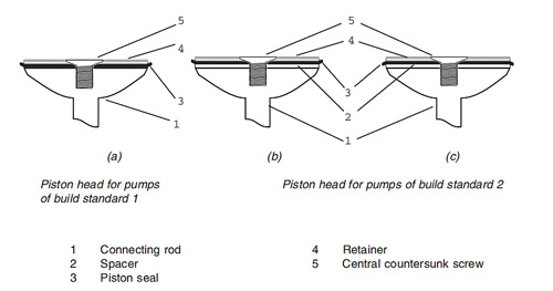
Build standard 2 introduced a profiled spacer on the piston crown enabling the piston seals to be reversed for more effective vacuum generation. A new style of cylinder, with hard anodising and high polish, improved seal wear and reduced leakage. To keep stroke lengths correct a similar profile spacer is used on the pressure piston. Improvements to piston alignment with the piston seal changes has increased the servicing interval to 3000 hours. The output pressures can be sustained at 3.5 bar and 20 mbar absolute
Noise reduction has been achieved by increasing the filter area of the pressure air intake; air is drawn from inside the crankcase through an end-mounted porous plate. A robust three-axis anti vibration mounting reduces the effects of external vibration. Originally designed and developed for the ADTS 405F, this mounting fits into a surface mounting adaptor cradle.
New component list:
Item:3-10a†;Description:.Cooling assembly, water trap [post MOD 04];QTY:ref
Item:3-10a†;Description:..Body, cooler;Manufacturer's Part Number:AS405-17-1728M1;QTY:1Item:3-10a†;Description:.Screw, M4x 30, QTY:4
Item:3-10a†;Description:.Pipe assembly QTY:1
Item:3-10a†;Description:.Cable looms, assembly;Manufacturer's Part Number:AS405-24-1728M1;QTY:1
Procedure:
1.Unscrew and disconnect the right-angled output union from the pressure output of the pump/ motor assembly and collect the bonded seal.
2.Cut the tyrap securing the water drain filter.1.Unscrew and disconnect the right-angled output union from the pressure output of the pump/ motor assembly and collect the bonded seal.
3.Release the water drain trap from the spring clip, remove the drain pipe from the clear nylon bowl. Discard the water drain trap. Unscrew and remove the two screws securing the spring clip, discard the screws and spring clip.
4.Unscrew and remove the clips retaining the cooling coil. Discard the cooling coil and clips.
5.Front panel;Note:Take appropriate precautions to prevent swarf contamination of the unit from the following procedure. [Service tip - turn unit upside down when drilling.]
Mark out the front panel using the dimensions detailed in figure 3-4. Drill four M3 holes in the front panel.
6.Locate the new water cooler assembly and secure to the front panel with the four screws and washers.
7.Connect the wires for the pressure bleed valve solenoid on the water/cooler assembly as detailed in Figure 3-5.6.Locate the new water cooler assembly and secure to the front panel with the four screws and washers.
8.Connect the new pressure output pipe to the output port of the pump head. Connect the other end to the input connection of the water/cooler assembly.
9.Connect the new pipe to the output union of the water drain trap and the output connection of the rear panel. Connect the water drain pipe, make sure the other end locates in the grommet for correct venting of the water/cooler assembly.
10.Carry out an inspection of the unit look for loose connections and/or disturbance of the internal components.
11.Carry out a Standard Serviceability Test detailed in Chapter 5.
Parts Lists Build Standards 1, 2, 3 and 4
| Item/Ref. | .PSU, (Mod 00) [superseded by item 2a] | Manufacturer's Part Number | QTY |
| 1-1 | Pump unit PV103 [Build standard 1][OBSOLETE superseded by BS4] | IA2127-1-V0 | ref |
| -2† | .PSU, (Mod 00) [superseded by item 2a] | ADTS405-1728-86-M0 | NP |
| -2a | .PSU, (Mod 01) [supersedes item 2] | ADTS405-1728-73-M1 | 1 |
| -3† | .Controller, motor speed [superseded by item 3a] | ADTS405-1728-74-M0 | NP |
| -3a | .Controller, motor speed [supersedes item 3](matched with item 2a) | ADTS405-1728-74-M1 | 1 |
| -4 | .Pump and Motor Assembly [OBSOLETE superseded by item 4-3] | NP | |
| -5 | .Filter, fan [OBSOLETE superseded by item 4-8] | NP | |
| -6 | .Fan assembly | ADTS405-1728-77-M0 | 1 |
| -7 | .Indicator, elapsed time | ADTS405-1728-82-M0 | 1 |
| -8 | .Switch | ADTS405-1729-92-M0 | 1 |
| -9 | .LEDand Clip | ADTS405-1729-91-M0 | 1 |
| -10 | Housing, mist filter [OBSOLETE (pre mod 04) superseded by item 4-10] | NP | |
| -11 | Block, cylinder [set of 4] [OBSOLETE] | NP | |
| -12 | Fitting, bulkhead AN6 [OBSOLETE -see fig 2 item 19] | NP | |
| -13 | Fitting, bulkhead AN4 [OBSOLETE -see fig 2 item 20] | NP | |
| -14 | Mounting, antivibration | ADTS405-1728-16-M0 | 4 |
| -14a † | Item deleted | ||
| -15 | .Connector, filter, power supply | ADTS405-1728-07-M0 | 1 |
| -16a † | Kit, fuse/o-ring | ADTS405-1728-36-M0 | 1 |
| -17a † | . Fuse T5.0A/250V HBC 20mm | NP | |
| -18a † | Kit, pump seals | ADTS405-1728-63-M0 | 1 |
| -19a † | Kit, hose [OBSOLETE} (see item 5.2 in list of accessories) | NP | |
| -20 | .Kit, pneumatic | ADTS405-1728-21-M0 | 1 |